-
Mailen Sie uns
yu.li@tiger-transformer.de -
Rufen Sie uns
+49 151 7050 5516 -


Mailen Sie uns
yu.li@tiger-transformer.deRufen Sie uns
+49 151 7050 5516
Continue to talk about the rotation.
In the previous article, we learned about Ampere's law and Faraday's law of electromagnetic induction.
Two new terms are introduced today: Hall effect and magnetoresistance effect.
01.
Hall effect and magnetoresistance effect
Magnetoresistance The definition of Magnetoresistance Effects: refers to the phenomenon that the resistance value of some metals or semiconductors changes with the change of the external magnetic field. When carriers in a metal or semiconductor move in a magnetic field, they are subjected to the Lorentz force generated by the change of the electromagnetic field, resulting in a magnetoresistance effect.
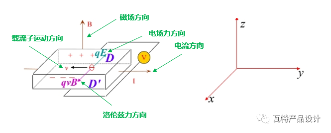
As shown above, put a semiconductor sheet under the magnetic induction In the magnetic field of B, if currentI is passed along the positive direction of the y-axis, the carriers in the semiconductor will be deflected by the Lorent magnetic force (using the left-hand rule to judge the direction of the force). The accumulation of charges in the x direction produces a Hall electric field, thereby generating a Hall electric field, and this effect is also called the Hall effect.
Because the moving speed of the carriers is not the same, but satisfies a certain statistical distribution, then a part of the carriers will be deflected to the D and D' sides of the above figure. The deflection reduces the number of carriers moving along the direction of the applied electric field (y direction), thereby increasing the resistance, which is the magnetoresistance effect.
The magnetoresistance effect causes the magnetic field lines, that is, the magnetic induction lines, to always follow the path of the least reluctance, just as the current will always choose the path of the least resistance to pass through.
For example:
If there is an air gap between two silicon steel sheets (one is like a stator and the other is like a rotor), and the air gap is changing, in a silicon steel A coil is wound on the chip, and a current is passed through, then according to the above Ampere's law, a magnetic field will be generated, and then according to the principle of Magneto-resistance effect, the silicon steel part as the rotor will be Will be forced to move, so that the path of the magnetic field lines is the shortest.
The new energy car motor resolver mostly adopts the reluctance type.
02.
Transformer
The rotary transformer is also a kind of transformer, so what is a transformer ? Let's review again:
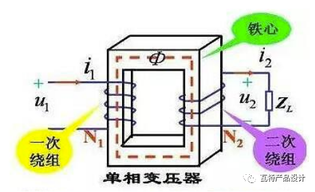
Transformer (Transformer) is a device that uses the principle of electromagnetic induction to change AC voltage. The main components are primary coil, secondary coil and iron core (magnetic core).
The coils on both sides of the transformer are also called the primary side and the secondary side.
The primary side corresponds to the primary coil, which is the input side of the voltage; the secondary side corresponds to the secondary coil, which is the output side of the voltage after the voltage is converted by the transformer.
The voltage ratio on both sides is related to the number of coil turns on both sides. The formula is: V1/V2=N1/N2.
03 .
03 .
03 .
03 p>
The role of the resolver
We know that the main function of the electric control is a inverter, which converts direct current into alternating current, thus giving The motor provides the drive current. In addition, it can also control the frequency and sequence of the three-phase alternating current, so that the speed and direction (forward and reverse) of the driving motor can be changed.
The role of the resolver is to accurately measure the position, speed and direction of rotation of the motor rotor, and transmit these signals to the electronic control, and the motor is controlled by the software control algorithm.
04.
Structure and Working Principle of Resolver
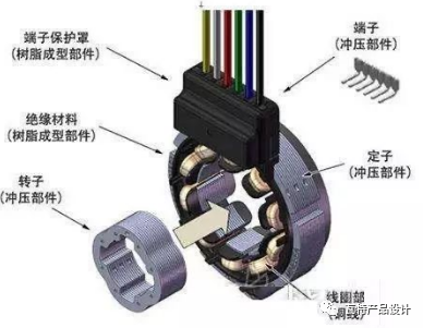
A resolver is actually a small motor that includes a stator, rotor and coil windings.
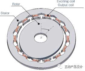
The core material of the stator and rotor is high magnetic permeability High-quality silicon steel sheets or iron-nickel alloy sheets are punched, insulated, and stacked.
There are generally three sets of windings, namely the excitation winding and the two-phase output winding, which are respectively fixed in the stator slots.
The magnetic pole shape of the rotor is also special, which makes the rotor and The air between the stator cores has a sinusoidal shape, and when the rotor rotates, the air gap is constantly changing, but the two-phase output winding signals have a sinusoidal relationship.
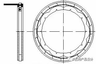
Next, let's understand the winding wiring, refer to the figure below. It can be seen that the exciting coils are connected in reverse series one by one magnetic poles, and the output winding 1 and winding 2 are connected in reverse series with a magnetic pole in the middle. The eccentric cam in the middle is the rotor, and the air gap distance between it and the iron core determines the strength of the magnetic field. The magnetic field strength is inversely proportional to the air gap spacing.
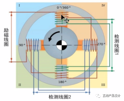
In addition, the winding has 6 external leads. 2 temperature lead wires, so the general resolver has 8 external output signals. The general structure can refer to the following figure:
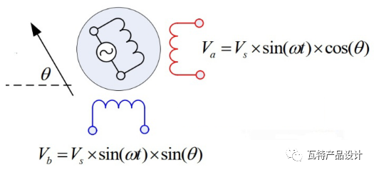
If the excitation coil input is the sinusoidal excitation current sinωt, the angle θ between the rotor and the stator, then the signal of the sine output winding is sinωtsinθ, the signal of the cosine output winding is sinωtcosθ, and the voltage calculation is multiplied by the original excitation voltage , as shown below:
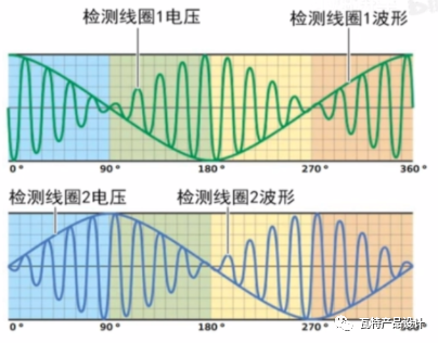
If you look at the waveform of the output voltage , the phase angle difference between the sine and cosine output signals is 90 degrees, the VCU of the vehicle can calculate the position of the rotor by detecting the output voltage values of the two windings, and then calculate the position of the rotor through the waveform RPM, that's how a resolver works.
Last words
Okay, about the introduction of the resolver, I will write it here first.
Let's summarize:
First of all, I will take you to review:Ampere's law, law of electromagnetic induction, Hall effect and magnetoresistance effect.
Then introduce the knowledge of transformer, so as to understand that the resolver is also a kind of transformer.
Then introduces the basic structure of the resolver in detail:stator, rotor and winding.
The winding contains three more:excitation winding, two output windings (sine and cosine).
Finally, the vehicle VCU calculates and detects the voltage values of the two output windings of the resolver, thereby calculating the position of the motor rotor, and then calculating the rotor speed.